
80 Meter NVIS Antenna – Don’t Get Hung Up on Theory
UPDATE: Since this article was originally published, I went to the pesky South Arm NEFR stage and did an official 80-meter NVIS test with four other seasoned operators. CLICK or TAP HERE to read about the successful test and listen to the actual audio recording of the test.
Watch the following video to see how to build and erect a basic 80-meter NVIS antenna. After watching the video, please read the field test stories below the video as this design flies in the face of a theoretical 80-meter NVIS antenna design.
I’m the Chief of Communications for the New England Forest Rally and we need to rely on NVIS to solve a tough comms problem. CLICK or TAP HERE to read about it.
CLICK or TAP HERE to download a simple plan and material list of this antenna.
CLICK or TAP HERE to purchase the banana post BNC connector to build the NVIS antenna in the video below.
IMPORTANT NOTE: Since the video was created, I’ve switched to wonderful fiberglass electric-fence posts instead of the cumbersome wood stakes you see in the video.
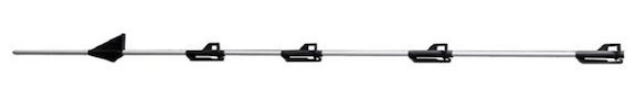
I rotated the image 90 degrees so it would fit on the page better. The left end has a point that drives easily into damp soil. The black fittings accept the NVIS wire with ease. You don’t have to feed the wire through them, just drop through the notch. CLICK or TAP HERE to order eight of them.
CLICK or TAP HERE to get the affordable fiberglass posts. You’ll need 8 of them. You may be able to get them locally at a Tractor Supply store – and for less money.
Field Testing Tales
I was first introduced to this simplistic antenna in 2014 when I first started to learn CW. My mentor Jim Cluett, W1PID told me about his discovery of this low-to-the-ground antenna because he used it to get onto the NH-VT traffic net each night from his home in Sanbornton, NH.
We have a very difficult communications issue on one of our stages in South Arm, Maine at the rally. CLICK or TAP HERE to read about this tough comms problem. This year, 2019, was my second year in the job and I decided to do an experiment with 80 NVIS with two other operators.
I set up this same antenna as you see in the video above, but it was even more wretched. It averaged just 18 inches above the ground. I was transmitting at 13 watts on my Elecraft KX3 and two other operators heard me crystal clear ten miles away. It’s very likely the success was due to a ground wave.
However, during the same test, my mentor 100 miles away was monitoring the test out of general interest and he heard me just fine. I had a conversation with him while I was waiting for my fellow operators in Maine to set up their 80-meter NVIS antennas just 10 miles away.
We were operating phone (SSB) because that’s how the comms would happen during the race. I’m doubtful my meager 13-watt signal would travel 100+ miles via ground wave over some semi-mountainous terrain, but I could be wrong. It absolutely might be why the other two operators were able to hear me and I hear them just ten miles away.
A week prior to the test at South Arm during July of 2019, I did a similar test with this antenna design in my backyard. That antenna was probably only 30 inches above the ground. I had successful SSB communications with my mentor who was 8 miles away and another old friend, Dave Benson, K1SWL, who was about 40 miles away. Once again, I was fairly low power, 10 watts, and I don’t believe that ground wave would make it 40 miles.
If you’re an antenna expert and can point me to a document that really shows how far an 80-meter ground wave can travel at different power levels, I’d be forever grateful. Please add those links in the comments below. 73 Tim Carter – W3ATB
Tim — Congratulations on the QST July 2023 article about the 80 meter NVIS net at NEFR! Despite having a General class license, I have only had the finances for an old, but excellent, Kenwood HF hybrid — not necessarily a “boat anchor”, but not mobile by any stretch of the imagination! I am swapping auto repair work towards a used Yaesu mobile HF rig with a local radio club member… Should have it by summer’s end. I noted your comment about starting to learn CW; how has that progressed? While I have generally good hearing, I have had trouble discriminating the “dots from the dashes”, so I have been hesitant to push further. Once again, congratulations on the QST article!!!
TNX for your kudos! You might also look around your garage or basement for things you no longer want or need. I’ve been purging stuff that I thought was useless, but others feel there is value. I’ve sold many hundreds of dollars of stuff using Craigslist and the garage-sale groups on Facebook.
I’ve been doing CW now for almost 10 years and I have a head-copy speed of about 15 WPM. Get one of the apps like the Koch Trainer and see if you can hear the dihs and dahs. Be SURE to read my story here on this blog about Teaching Kaylee Morse Code.
“Koch Trainer”, got it, will look into it. I have a beautiful old straight key that came with my Kenwood TS 820-S system, it really is a shame that it just sits there… Not to mention the operational advantages of adding CW… Like you, I have begun looking around the whole house to clean and organize. Our club experimented with a new wire antenna design for an emergency comms exercise at our regional airport — https://w6nbc.com/articles/2020-TBDdoubledelta.pdf We have some work to do to get it efficient, but it was great to try something new. Blessings to you and yours.
I really enjoyed this article… “Theory” is called “Theory” for a reason, and there’s always the “optimal” part as well. Every antenna is a compromise of some sort…Directionality, dBd / dBi gain, bandwidth, takeoff angle, et cetera… and as we all know, everything affects everything when it comes to an antenna system’s performance.
You never claimed this is perfect or that it would work everywhere, you just showed that it worked for you and your team. I have a few antennas up in the yard that, in theory or according to the modeling, shouldn’t work in certain directions, or shouldn’t work on certain bands, et cetera… But they do, and they work well enough to suit my needs most of the time. Seriously, you SHOULD write that book… Having seen a guy load up a turkey-roasting pan and make contacts, I bet you’ll have some cool ideas in there!
For your antenna with both legs 65’-7” what’s the optimal phone frequency 3.560 mhz? I don’t have an analyzer
https://www.hamradiosecrets.com/antenna-calculator.html
My 80m NVIS antenna at home is “permanently” thumbtacked to the privacy fence 4′ off the ground. This antenna works fantastic for local comms around Colorado (weekly rag chews and ARES nets with check-ins from Wyoming to New Mexico). I’ve even worked stations on the east coast with it on SSB and CW. For every 1 that told me it wouldn’t work at all, I’ve logged 5 contacts just for them 🙂 As a bonus, it loads up easily on 17m and I’ve made many digital contacts into Europe on it.
In fact, I’m 99.999% sure that I got my idea from your video some time ago. So, thank you!
Bob, W0BNC
I can’t seem to model this in mmana-gal basic.
Any suggestions. It just comes out with stupidly high swr. At least at that height.
Also for 0.15 -0.25 lambda above the ground.
0.15 X 80 m = 12m
Anyone know where I can get 12m high electric fence posts…. And you need how many? At least 10? And they need to be strong enough not to bend… Even with fibreglass squid poles it would be a challenge.
I just think all that’s not practical and in any case not something you could put in your back pack or quickly erect in the neighbourhood park.
Anyway I’m thinking end fed inverted V so the the 12m high squid pole is just supporting the middle of the wire and you don’t have all the supports.
Michael,
I think you might want to go back up and read the secondary headline just above the word UPDATE in red.
The antenna works. Once again at the New England Forest Rally a month ago 12 operators deployed the antenna and talked with one another as if they were sitting at the same table in a quiet restaurant.
The absolute simplest way to use this in the field from a backpack is the two lengths of wire, the binding post adapter and that’s it. You throw a water bottle over a branch or somehow get the binding post adapter 10 or 12 feet in the air. You then stretch out the two legs of the dipole and have them secured to anything else about 4 feet in the air at each end.
You now have a shallow inverted V. It will perform beyond your wildest dreams. Yes, you’ll need a tuner to get a 1:1.2 match or so.
Try this and report back.
In EZNEC, I had to change the ground from perfect to Real/High Accuracy, and then I had a nice dip down to 1.17:1. I’m at 12 ft above the ground.
The attentive reader will notice that, in the video, the antenna is built over a meadows near a lake. Therefore the ground is wet and a good conductor. This helps explains why it works well for you and less so for others… 😉
Jerome,
I hate to drop this on you, but that has little to do with its performance. If your hypothesis was correct, explain to me why this test was successful in dry, rocky soil: https://w3atb.com/nefr-south-arm-80-meter-nvis-test/
Then I’ll go one step further. Nine months later ten operators set up at the same location spread out over 30-40 square miles and we had perfect comms. It was DRY AS AN OLD BONE.
Just came across this Tim, very interesting. I now intend to string a similar length but with the centre at 15 feet (height of the centre of my tree) and two 4 feet high electric fence posts, “just to see what results I get”. Love to experiment having just finished building a pre-amped receiving loop and 90 degree rotator from a servo and the junk box.
Garry M0MGP
Garry,
You’ll get stellar results with that shallow inverted V. Come back and give us a full report! I’m happy to publish a photo of your antenna here above if you send it to me.
“Engineering theory” has a lot of flies in its face. 😉
I HAVE A ACRE LOT NOT BEING USED AS THAT SAID I DONT WANT A HUGE ANTENNA UP IN THE AIR. WATCHED YOUR VIDEO ON NVIS AND MY BRAIN RAN WILD I HAVE OVER A THOUSAND FEET OF NUMBER 6 ALUM STRAND INSULTLATED WIRE AND
WOULD LIKE TO TRY TO BUILD A 160/80 METER ANTENNA LIKE THE ONE IN YOU VIDEO ONLY ON A GRANDER SCALE MY SHACK IS BOUT 100 FEET FROM WHERE ANTENNA WOULD START IN ONE DIRECTION I HAVE MANY QUESTIONS LIKE DO I HAVE TO FEED FROM MIDDLE ID LIKE TO TRY END FED BUT DONT KNOW MUCH ABOUT IT I HAVE ROUND FENCE POST GOING THE LENGTH OF THE LOT STRAIGHT ALL AROUND PLEASE ANY IDEAS ON THIS WOULD BE HELPFULL ALSO ANY INSIGHT ON JUST WHAT TO DO ID LIKE TO GET ON THE PHONE SECTIONS OF 80 AND 160 METERS ALSO I HAVE A MOTOROLA TUNER THAT I CAN SET UP OUT NEXT TO ANTENNA WITH LITTLE TO NO PROBLEM MY BEST REGARDS KEVIN
Feeding from the end is possible but it will be easier to do from the middle because the impedance at the middle is much lower. The impedance at the end is very high and requires a good ground.
As a friend of mine often says, “The best antenna is the one that works.” This might not be the best for ultimate performance, but if it suits our needs at NEFR, it’s served it’s purpose.
certainly an interesting idea.
a repeater is definitely a point of failure.
My concern would be QRM from stations hundreds of miles away while trying to provide a safety net for cars at competition speeds.
Roger
kb1mkd
Roger,
80 meters is pretty dead during daylight hours. There’s lots of bandwidth to find places to operate without QRM. You have the same issue no matter what frequency you decide to use.
Roger, In the process of bashing Tim’s antenna, Jim answered your question:
“Yes, one will work just a few feet above ground and will be quieter than one higher up, but at what cost? Quieter simply because of ground losses.” (Jim)
There are actually two losses to the lower antenna. Ground losses and low angle or radiation losses. If the antenna does not hear as much, it reduces the QRM. Since Tim’s purpose of the antenna is to communicate to a specific group of people in a specific area. As long as the antenna communicates to these people, anyone else it rejects is not a “cost”, as Jim calls it, but an added benefit.
Buck,
BINGO! I just want the antenna to work in a 12-mile radius for the most part. Just like in a fox hunt. You don’t use an omnidirectional antenna in that game and win.
Loved all the ham talk here although I come here most for building. I do have a warm place in my heart for ham radio and the people who practice it. It reminds me of a Dave Barry quote: “Guys like to do stuff! That explains everything from mailbox vandalism to the space shuttle.” Ham has a much deeper purpose in mind but I thing the analogy still works. Keep on sharing!
I worked on a deep ground penetrating radar project at the Air Force Research Lab in Rome, NY for a number of years. A lot of fiddling went into making MW to UHF antennas that effectively radiated into the ground. And wideband, portable, and a few other things. The important thing to understand about antennas over a dielectric half-space is that the dielectric constant of rock might be 4-8, and that of water is 80. So, your tuning changes drastically as you change the height, and above different soils or rock. Sitting on top of the surface, you can use the equations for stripline, but above that, there’s too many terms to figure on the back of an envelope. If you point a VHF yagi into the ground, the directors “lengthen” into directors somewhere less than a wavelength away.
It looks like you didn’t use a balun anywhere, so it would be interesting to see what happens when you run the coax through some ferrites. Also, how about the polarization between xmit & rcv?
You probably have a lot of ground wave propagation, because your antenna looks a lot like the Navy’s VLF setup in Cutler, Maine. Except you don’t have a megawatt transmitter and aren’t at 24 KHz.
I run that antenna into my Elecraft KX3 that has an internal tuner. Since it’s a balanced dipole, the small tuner has no issues giving me a 1:1 or 1:1.5 SWR. Great story you shared! TNX for doing that!
Great article and simple set up. I live in a place where I have lots of space but I have few optimal places to string antennas. My 40/75m trapped dipole is strung from about 25 feet up at one end with the other end trap being at 10 or so feet with the 75m stub down to about 3 feet. I call it the “dog leg dipole” and I’ve worked all over the world with the configuration on 40m and a significant number of countries on 75.
All of my antennas would be considered compromised designs due to simple things like not having a tower, large trees or natural structures in convenient places. But I’ve strung verticals, dipoles, deltas and quads in strange configurations and gotten very good results. So although the “rules say”, at the end of the day if it works, don’t knock it.
John,
Exactly. There are the purists like Jim above, and then there are the rapscallion antenna stringers like us. INSERT Happy face emoticon here.
Some folks in Silicon Valley who like to play with Mil equipment set up and NVIS similar to what you have and got excited because they proved it would work when they were able to contact colleagues 10 miles away.
I worked with an engineer “back in the day” who was a also a ham. He told me a tale of soaking his Mom’s cotton clothes line in salt water, then loading ’em up and made HF contacts until the “element” resistance dried up the moisture. I saw a YouTube video once upon a time where a couple of guys loaded two 50’s vintage Buicks parked nose to nose, making contacts afterwards. Radio is PFM (pure frickin’ magic) where wierd stuff can sometimes work.
I noted the distance of the folks you contacted with your NVIS, all approx 100 miles away and less. You probably know that max theoretical reach for NVIS to be 400-500 miles. I’ve gotten good reception and S9 reports from stations at 400 miles (Sacramento area and Truckee, CA area to Tehachapi, CA. While camping a few miles north of Truckee with another ham, we experimented with the performance difference between my inverted V AS-2259 (elements cut for 40M) and a 40M horizontal dipole almost colocated. Feed point for my NVIS was 15′ (very close to the .15 lamda for 7MHz) and elements sloping at 45 deg. Feedpoint to my friends dipole was similarly at 15′. Expectation was the horizontal dipole would outperform my inverted V connecting to the Tehachipi station. Nope. My antenna had a report of S9, my friends antenna S7.
Another occasion I set up for 40M connections to Winlink HF (40M) gateways while in the Sierra for an equestrian event. Had a perfect, <1.5:1 VSWR with the NVIS over grass in a local park. In the Sierra, over dry, rocky ground, the VSWR was crap.
Just goes to show that under varying conditions up to and beyond standing on your left foot and putting your right pinky into your left ear can get good results. However, for reliable results, one goes with what the engineers say, else the AS-2259 (admittedly, a compromise antenna for use in a combat theatre) would be strung out a few feet off the ground to trip sappers as they tried to sneak into an HQ camp 😉
Well, I have to respectfully disagree with your last sentence. The antenna you see in this video is reliable. Perhaps you overlooked the part of the story where my mentor used the antenna to check in repeatedly with the NH-VT traffic net.
No worries, you do what’s best for you and for our NEFR rally where we need an antenna we can deploy in minutes, we’ll use this antenna. Believe me, I’ll report back next year after the 2020 NEFR where eight HF operators will be on that South Arm stage using NVIS, ground wave, or pure magic.
Your height above ground for a NVIS antenna flies in the face of engineering theory for an NVIS antenna. In short, an NVIS needs to be .15 to .25 wavelengths above ground for good performance. Yes, one will work just a few feet above ground and will be quieter than one higher up, but at what cost? Quieter simply because of ground losses.
About the time I built my inverted V modeled on the Mil AS-2259 I studied (including consultation with RF engineers) the why’s and wherefore’s of NVIS height above ground. ALL verified the optimal height at .15-.25 lambda above ground
There are numerous references re NVIS engineering including this one as a starter:
Military HF Radio Communications and Near Vertical Incidence Skywave Propagation
https://www.youtube.com/watch?v=4EadY6eDKhs&t=2s
Jus’ sayin’
Jim,
You’re absolutely correct about the theory. I decided to add much more content above AFTER you posted your comment. The content helps explain the context of the antenna and how well it actually performs.
One of my projects with HF comms, as crazy as this sounds, is to put up the most wretched antenna configurations possible to see what works. Who knows, I may write a short book about it.
Wretched Antennas You’d Never Think Would Work
by: Tim Carter W3ATB